Characteristics and application differences of conductors of high temperature cables single core wires and cables

Conductor characteristics
·Single conductor: single core wires and cables are composed of a single conductor, which can be solid (single copper wire or aluminum wire) or stranded (multiple strands of fine wires twisted together).
·Larger diameter: Compared with multi core cables, the conductor diameter of single core cables is usually larger to ensure sufficient current carrying capacity.
·Mechanical strength: Solid conductors have higher mechanical strength and are suitable for fixed installation; stranded conductors are more flexible and suitable for occasions that require frequent bending.
Application scenarios
·Fixed wiring: such as fixed electrical wiring in homes and office buildings.
·Power transmission: Commonly used conductors in high-voltage transmission lines because single core conductors can provide greater current carrying capacity.
·Lighting circuits: Indoor lighting circuits, etc.
multi core wires and cables
Conductor characteristics
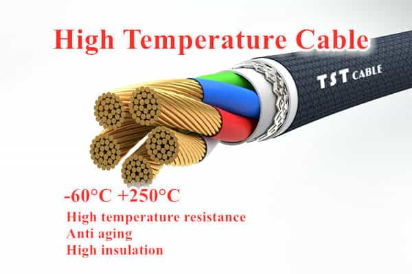
·Multiple conductors: multi core wires and cables are composed of multiple conductors, which can be arranged in parallel or twisted together.
·Flexibility: The design of multiple conductors makes the cable more flexible and easy to bend and install.
· Diversity: multi core cables can integrate multiple conductors to achieve multiple functions, such as power transmission, signal transmission, etc.
Application scenarios
· Electrical equipment connection: such as the connection between motors, control panels, switch cabinets and other equipment.
· Data transmission: data cables and telephone lines in computer networks.
· Control lines: signal transmission lines in industrial control systems.
· Mobile equipment: suitable for equipment that needs to be moved frequently, such as elevators, cranes, etc.
Conductor materials
· Copper conductor: Copper is the most commonly used conductor material because it has good conductivity and high mechanical strength.
· Aluminum conductor: In some cases, aluminum is also used as a conductor material, especially in high current applications, because aluminum is lighter than copper and has a lower cost, but its conductivity is slightly worse.
Conductor structure
· Solid conductors: Suitable for fixed installation because they have high mechanical strength and low resistance.
· Stranded conductors: Made of multiple strands of fine wires, this structure makes the conductor more flexible and suitable for applications that require frequent bending.
Selection basis
When choosing single core or multi core wires and cables, the following factors need to be considered:
· Current demand: single core cables are usually selected for occasions with large current loads.
·Installation environment: multi core cables are more advantageous in situations where frequent bending or movement is required.
·Usage function: If multiple functions need to be integrated, such as power and signal transmission, multi core cables are more suitable.
·Cost considerations: single core cables are less expensive in some cases, while multi core cables are more advantageous in flexibility and versatility.
Summary
single core wires and cables and multi core wires and cables each have their own applicable scenarios. single core cables are suitable for situations with large current demand and fixed installation; while multi core cables are more suitable for applications that require flexibility and multi-functional integration. Choosing the right type of wire and cable can ensure the safety and reliability of the electrical system.
single core wire and cable conductor technical parameter reference table
TST CABLES has compiled a technical parameter table for single core and multi core solid conductor cables, stranded conductors, and soft conductors. If you don’t have the size specifications you want, please email us.
1 high temperature cables Scope
This standard specifies the standardized nominal cross-section, number of single wires, single wire diameter and resistance value of conductors for cables and soft wires from 0.5-2000mm2.
This standard does not apply to conductors for communication purposes. Only when the cable standard specifies, it is applicable to conductors for specially designed cables, such as conductors for pressure cables, conductors for special soft welding machine cables, or conductors for special soft cables with special short pitch.
2 high temperature cables Classification
Conductors are divided into four types: Type 1, Type 2, Type 5 and Type 6.
Table 1 Technical parameters of Type 1 solid conductors for single core and multi core cables
| Nominal cross sectionmm2 | Maximum resistance of conductor at 20℃ Ω/km | ||
| Round copper conductor | Round or shapedaluminum conductors | ||
| No metal plating | Metallization | ||
| 0.5 | 36.0 | 36.7 | – |
| 0.75 | 24.5 | 24.8 | – |
| 1 | 18.1 | 18.2 | – |
| 1.5 | 12.1 | 12.2 | 18.12) |
| 2.5 | 7.41 | 7.56 | 12.12) |
| 4 | 4.61 | 4.70 | 7.412) |
| 6 | 3.08 | 3.11 | 4.612) |
| 10 | 1.83 | 1.84 | 3.082) |
| 16 | 1.15 | 1.16 | 1.912) |
| 25 | 0.7271) | – | 1.20 |
| 35 | 0.5241) | – | 0.868 |
| 50 | 0.3871) | – | 0.641 |
| 70 | 0.2681) | – | 0.443 |
| 95 | 0.1931) | – | 0.320 |
| 120 | 0.1531) | – | 0.253 |
| 150 | 0.1241) | – | 0.206 |
| 185 | – | – | 0.164 |
| 240 | – | – | 0.125 |
| 300 | – | – | 0.100 |
| See 4.1.2 of this standard;1.5mm2-16mm2 only has round aluminum conductors, see 4.1.3 of this standard. | |||
4.2.2 The single wires in the conductor shall have the same nominal diameter.
4.2.3 The number of single wires in the conductor shall not be less than the corresponding minimum number specified in Table 2.
The conductor with a cross-section of 1200mm2-2000mm2 does not specify the minimum number of wires.
4.2.4 The resistance of each core conductor at 20℃ shall not exceed the maximum value specified in Table 2.
4.3 Compacted stranded round conductors and twisted shaped conductors shall meet the following requirements.
4.3.1 The conductor shall be composed of the following materials:
– Annealed copper wire without metal plating or metal plating;
– Uncoated aluminum or aluminum alloy wire.
The cross-section of the compacted stranded round aluminum conductor shall not be less than 10mm2, and the cross-section of the twisted shaped copper or aluminum conductor shall not be less than 25mm2.
4.3.2 The diameter ratio of two different single wires in the same conductor shall not exceed 2.
4.3.3 The number of single wires in the conductor shall not be less than the minimum number specified in Table 2.
The conductor with a cross-section of 1200mm2-2000mm2 does not specify the minimum number of wires.
4.3.4 The resistance of each conductor at 20°C shall not exceed the maximum value specified in Table 2.
Table 2 Second type of stranded conductor for single core and multi core cables
| NominalCross sectionmm2 | Minimum number of single wires in a conductor | Maximum resistance of conductor at 20℃ Ω/km | |||||||
| Non-compacted round conductor | Compact round conductor | Formed conductor | Copper conductor | Aluminum conductor | |||||
| Copper | Aluminum | Copper | Aluminum | Copper | Aluminum | Non-metallized | Metallized | ||
| 0.5 | 7 | – | – | – | – | – | 36.0 | 36.7 | – |
| 0.75 | 7 | – | – | – | – | – | 24.5 | 24.8 | – |
| 1 | 7 | – | – | – | – | – | 18.1 | 18.2 | – |
| 1.5 | 7 | – | 6 | – | – | – | 12.1 | 12.2 | – |
| 2.5 | 7 | – | 6 | – | – | – | 7.41 | 7.56 | – |
| 4 | 7 | 72) | 6 | – | – | – | 4.61 | 4.70 | 7.41 |
| 6 | 7 | 72) | 6 | – | – | – | 3.08 | 3.11 | 4.61 |
| 10 | 7 | 7 | 6 | – | – | – | 1.83 | 1.84 | 3.08 |
| 16 | 7 | 7 | 6 | 6 | – | – | 1.15 | 1.16 | 1.91 |
| 25 | 7 | 7 | 6 | 6 | 6 | 6 | 0.727 | 0.734 | 1.20 |
| 35 | 7 | 7 | 6 | 6 | 6 | 6 | 0.524 | 0.529 | 0.868 |
| 50 | 19 | 19 | 6 | 6 | 6 | 6 | 0.387 | 0.391 | 0.641 |
| 70 | 19 | 19 | 12 | 12 | 12 | 12 | 0.268 | 0.270 | 0.443 |
| 95 | 19 | 19 | 15 | 15 | 15 | 15 | 0.193 | 0.195 | 0.320 |
| 120 | 37 | 37 | 18 | 15 | 18 | 18 | 0.153 | 0.054 | 0.253 |
| 150 | 37 | 37 | 18 | 15 | 18 | 18 | 0.124 | 0.126 | 0.206 |
| 185 | 37 | 37 | 30 | 30 | 30 | 30 | 0.0991 | 0.100 | 0.164 |
| 240 | 61 | 61 | 34 | 30 | 34 | 34 | 0.0754 | 0.0762 | 0.125 |
| 300 | 61 | 61 | 34 | 30 | 34 | 34 | 0.0601 | 0.0607 | 0.100 |
| 400 | 61 | 61 | 53 | 53 | 53 | 53 | 0.0470 | 0.0475 | 0.0778 |
| 500 | 61 | 61 | 53 | 53 | 53 | 53 | 0.0366 | 0.0369 | 0.0605 |
| 630 | 91 | 91 | 53 | 53 | 53 | 53 | 0.0283 | 0.0286 | 0.0469 |
| 800 | 91 | 91 | 53 | 53 | – | – | 0.0221 | 0.0224 | 0.0367 |
| 1000 | 91 | 91 | 53 | 53 | – | – | 0.0176 | 0.0177 | 0.0291 |
| 1200 | 3) | 3) | 3) | 3) | – | – | 0.0151 | 0.0151 | 0.0247 |
| (1400)1) | 3) | 3) | 3) | 3) | – | – | 0.0129 | 0.0129 | 0.0212 |
| 1600 | 3) | 3) | 3) | 3) | – | – | 0.0113 | 0.0113 | 0.0186 |
| (1800)1) | 3) | 3) | 3) | 3) | – | – | 0.0101 | 0.0101 | 0.0165 |
| 2000 | 3) | 3) | 3) | 3) | – | – | 0.0090 | 0.0090 | 0.0149 |
| The dimensions in brackets are non-preferred dimensions;See 4.2.1 of this standard;The minimum number of single wires is not specified. | |||||||||
5 Soft conductors (5th and 6th types)
Table 3 5th type of soft conductors for single core and multi core cables
| NominalCross sectionmm2 | Maximum diameter of a single conductor in the conductormm | Maximum resistance of the conductor at 20℃Ω/km Nominal | Nominal cross sectionmm2 | Maximum diameter of a single conductormm | Maximum resistance of conductor at 20℃Ω/km | ||
| Non-metallized | Metallized | Non-metallized | Metallized | ||||
| 0.5 | 0.21 | 39.0 | 40.1 | 50 | 0.41 | 0.368 | 0.393 |
| 0.75 | 0.21 | 26.0 | 26.7 | 70 | 0.51 | 0.272 | 0.277 |
| 1 | 0.21 | 19.5 | 20.0 | 95 | 0.51 | 0.206 | 0.210 |
| 1.5 | 0.26 | 13.3 | 13.7 | 120 | 0.51 | 0.161 | 0.164 |
| 2.5 | 0.26 | 7.98 | 8.21 | 150 | 0.51 | 0.129 | 0.132 |
| 4 | 0.31 | 4.95 | 5.09 | 185 | 0.51 | 0.106 | 0.108 |
| 6 | 0.31 | 3.30 | 3.39 | 240 | 0.51 | 0.0801 | 0.0817 |
| 10 | 0.41 | 1.91 | 1.95 | 300 | 0.51 | 0.0641 | 0.0654 |
| 16 | 0.41 | 1.21 | 1.24 | 400 | 0.51 | 0.0495 | 0.0495 |
| 25 | 0.41 | 0.780 | 0.759 | 500 | 0.61 | 0.0391 | 0.0391 |
| 35 | 0.41 | 0.554 | 0.565 | 630 | 0.61 | 0.0287 | 0.0292 |
Table 4 Sixth type of soft conductor for single-core and multi-core cables
| NominalCross sectionmm2 | Maximum diameter of a single conductor in the conductormm | Maximum resistance of the conductor at 20℃Ω/km Nominal | Nominal cross sectionmm2 | Maximum diameter of a single conductormm | Maximum resistance of conductor at 20℃Ω/km | ||
| Non-metallized | Metallized | Non-metallized | Metallized | ||||
| 0.5 | 0.16 | 39.0 | 40.1 | 50 | 0.31 | 0.368 | 0.393 |
| 0.75 | 0.16 | 26.0 | 26.7 | 70 | 0.31 | 0.272 | 0.277 |
| 1 | 0.16 | 19.5 | 20.0 | 95 | 0.31 | 0.206 | 0.210 |
| 1.5 | 0.16 | 13.3 | 13.7 | 120 | 0.31 | 0.161 | 0.164 |
| 2.5 | 0.16 | 7.98 | 8.21 | 150 | 0.31 | 0.129 | 0.132 |
| 4 | 0.16 | 4.95 | 5.09 | 185 | 0.41 | 0.106 | 0.108 |
| 6 | 0.21 | 3.30 | 3.39 | 240 | 0.41 | 0.0801 | 0.0817 |
| 10 | 0.21 | 1.91 | 1.95 | 300 | 0.41 | 0.0641 | 0.0654 |
| 16 | 0.21 | 1.21 | 1.24 | ||||
| 25 | 0.21 | 0.780 | 0.759 | ||||
| 35 | 0.21 | 0.554 | 0.565 | ||||
If you need to customize the above specifications of single core or multi core high-temperature cables, or cables of other specifications, you are welcome to contact TST CABLES engineers by email (email: lixiangchao@testeck.com)
Also available in:
English


